Author: Ali Kosari Mehr
Sputtering/Co-sputtering
Delineating the dominant trend of the sputtering process with simplification, one can divide the process into six steps:
a) The deposition chamber is vacuumed (typically until the pressure reaches a value with the order of 10-6 torr)
b) The sputtering gas (e.g., the inert gases of argon, xenon, etc.) is introduced to the chamber.
c) The voltage required for the generation of glow discharge – a type of plasma – is applied between two electrodes positioned in the chamber.
d) In the generated glow discharge, free electrons collide with the atoms of the sputtering gas, causing electrons to be separated from the atoms (i.e., the formation of positive ions of the sputtering gas).
e) Due to the applied voltage, the positive ions of the sputtering gas accelerate towards the cathode (the negative electrode).
f) Finally, as the result of the collision between the positive ions and the cathode, the atoms forming the cathode surface are separated and deposited on the substrate. Thus, the materials to be deposited are utilized as the cathode.
To date, various efforts have been made to improve the sputtering process. Accordingly, the first versions of the process just included a cathodic target and an anodic substrate holder/wall. Therefore, in these versions, the deposition rate was low and the voltage required for the generation of the glow discharge was considerably high. Moreover, the notion of substrates placed on an anodic substrate holder culminated in the vigorous bombardment of the growing films.
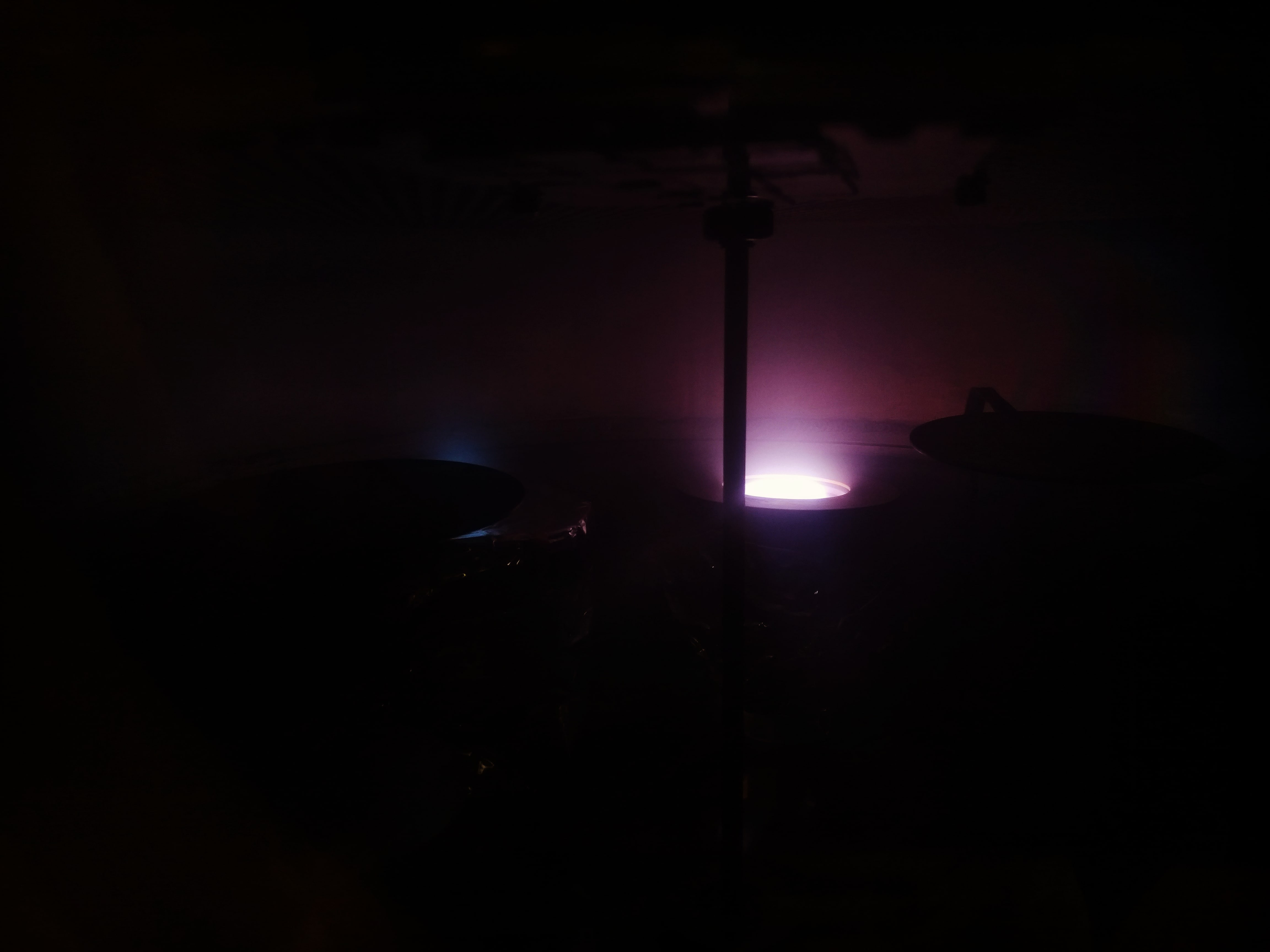
One of the first modifications was the utilization of a magnetic field in the cathodic area. In this regard, the use of a longitudinal magnetic field leads to the orbital motion of twined electrons around the magnetic lines, and consequently, decreases the number of free electrons being lost in the discharge region. Hence, the decrease in loss of the electrons results in an increase in collision probability between molecules and electrons, an increase in discharge current density, an increase in the deposition rate, a decrease in the pressure required for sputtering, and a decrease in the number of charged particles impinging on the substrate. Furthermore, another significant improvement was the invention of a device coined “sputter gun” in 1971. Accordingly, this device contains a cathode, an anode, and magnets (or even coils) in the device itself. Thus, since the substrate can be placed on a substrate holder not acting as an anode with the help of the device, the vigorous bombardment of the substrate can be prevented. It is noteworthy that sputter guns are compatible with various power supplies – i.e., radio frequency (RF), pulsed direct current (PDC), etc. – and various types of magnetic fluxes – i.e., balanced, unbalanced, etc. In addition, one can deploy (two or more) sputter guns attached to different power supplies to deposit thin films of complex multi-element compounds; this method is called co-sputtering.
Ultimately, one important point should be mentioned: reactive gases such as oxygen and nitrogen can be used along with inert gases such as argon in the sputtering process. Thus, since the ions of these gases are highly chemically reactive, they can be used to deposit thin films of oxides, nitrides, oxynitrides, etc.
References:
- Kosari Mehr Ali, Kosari Mehr Abbas (2021) Grid-Assisted Co-Sputtering Method: Background, Advancement, and Prospect. Plasma Chem Plasma Process 2021 413 41:713–744. Webpage
-
 20 Aug, 2022What is Auger electron spectroscopy?
 -
 13 Jul, 2022Classification of vacuum pumps
